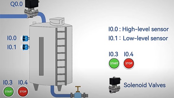
Maintaining a precise liquid level in a tank is a fundamental challenge in industries ranging from water treatment to food processing and chemical manufacturing. While the concept is simple, implementing a robust and automated control system requires careful planning and programming. This guide will walk you through the essential steps of programming a Programmable Logic Controller (PLC) to master this critical function, transforming a potentially erratic process into one of perfect automation.
Setup Components
Step 1: Define Your System Components
Before you write a single line of code, you must define your hardware. The control logic is built around these core components.
1. The Actuator: What device will control the flow? This is typically a pump (to fill) or a control valve (to fill or drain).
2. The Sensor: How will the PLC measure the level? Your choice dictates the control strategy:
Discrete Sensors: (e.g., float switches) provide simple ON/OFF signals at set points (e.g., Low-Level, High-Level). Ideal for simple ON/OFF control.
Analog Sensor: (e.g., a 4-20mA level transmitter) provides a continuous, precise level reading. Essential for advanced Proportional-Integral-Derivative (PID) control.
3. The Control Strategy:** Will simple ON/OFF control suffice, or do you need precise modulation?
tep 2: Design the Control Logic
Let's start with a simple and highly reliable ON/OFF Control strategy using two float switches.
Objective: Maintain the level between a Low-Level and a High-Level set point.
Logic:
If the Low-Level switch is activated (tank empty), TURN ON the pump.
If the High-Level switch is activated (tank full), TURN OFF the pump.
The pump should run continuously between these two points.
Step 3: Ladder Logic Programming Example
Here is a simple ladder logic diagram that implements the ON/OFF control. We assume the float switches are normally open (NO) and close when the level rises.
| Legend | |
|---|---|
I0.0 | High-Level Float Switch (Closes when full) |
I0.1 | Low-Level Float Switch (Closes when empty) |
Q0.0 | Pump Output Coil |
| Ladder Logic Diagram | ||||
|---|---|---|---|---|
| Network 1 | Start/Stop Circuit for Pump | |||
I0.1 | I0.0 | Q0.0 | ||
| (LOW) | (HIGH) | (PUMP) | ||
| `---- | ---- | / | ----( )----` | |
Q0.0 | ||||
| `---- | ----` |
Logic Explanation:
When the level drops below the Low-Level switch, `I0.1` (LOW) closes.
Because the tank is not full, `I0.0` (HIGH) remains closed (its normally closed `|/|` contact is "passing" power).
This energizes the pump coil `Q0.0`, starting the pump.
The sealing contact (branch around `I0.1`) keeps the coil energized even after the level rises above the Low-Level switch.
Only when the level reaches the High-Level switch does `I0.0` open, breaking the circuit and turning off the pump `Q0.0`. The cycle repeats when the level falls again.
Step 4: Level Up: Introducing PID Control
For applications requiring a precise, steady level (e.g., maintaining 75% full), ON/OFF control is too crude and causes rapid pump cycling.
This is where PID Control shines. You would use an analog level sensor (4-20mA signal) and program the PLC's built-in PID function block.
P (Proportional): Reduces the pump speed as the level approaches the setpoint, preventing overshoot.
I (Integral):** Eliminates any steady-state error, ensuring the level perfectly matches the setpoint over time.
D (Derivative):** Anticipates rapid changes in level (like a sudden drain) and responds faster.
Step 5: Integrate Safety and Best Practices
A functional program is not a professional one. For a robust, industrial-grade system, you must include:
Manual Override: Always include a Manual/Auto selector switch to allow for operator control during maintenance.
Alarms:Program critical alarms for a "Low-Low Level" (to prevent pump dry-running) and a "High-High Level" (for overflow prevention).
Interlocks: Ensure the pump cannot run if a downstream valve is closed or if there is a motor overload fault.
Conclusion
Programming a PLC for auto level control is a foundational skill in industrial automation. By starting with a robust ON/OFF logic and understanding the path to more advanced PID control, you can build systems that are not only functional but also efficient, precise, and safe. The key lies in a thorough understanding of your process requirements and meticulous attention to safety details. Now, go forth and tame that tide

2 Comment(s)
1
1
1
1
Leave a comment